The Z-Printer builds the prototype by making many thin cross sections of the model. A printerhead moves around the layer to deposit liquid binding material. A thin layer of powder is spread on top of this layer, and the process repeats. The exess powder is automaticly removed by the machine. Main advantage of using this method is the possibility to add color to the product. This allows you to representate different materials held by the product. The use is very easy, just load your .STL file in the Z-Print software and follow the instructions. The image bellow provides clear instructions of how to use the software.
After the printing is finished you start with removing powder around the printed part. This work is very precise and should be done with a soft brush. Once you have brushed away all surrounding powder you can take out the printer part and move it into the depowdering station. Here we use an air-blower to blow away the remaining powder. Once all the powder has been removed the epoxy can be applied. This is needed to give the product it's strength. Finally let the product dry and eventually you have your final product. The whole process can be watched in the following video.
The Roland 650 is a milling machine for rapid prototyping. The Roland 650 offers engineers and designers the opportunity to quickly and inexpensively turn concepts into three-dimensional prototypes, eliminating costly outsourcing. MODELA Player 4 is a CAM software application that can be used with the Roland 650. It is used to generate proportional 3D scaling, identify milling direction and to automatically generate and display the tool path. MODELA Player 4 supports tool changing when used with the Automatic Tool Changer (ATC) and automatic side cutting when used with the Rotary Axis Unit. To use the program you do as follow.
First export your model in your modeling software to a STL file, open this file in MODELA Player 4. There are three different views available. With the button aimed at with the arrow in the image below you can adjust from which sides the object should be cut.
Adjust the basic settings by changing the material, the scale, and the point of origin.
In the options window below you can set up the depth of the model.
The other tab shows the cutting angle
And the last one defines the cutting area.
As soon as these basic settings are set up, you can start adding milling actions. It depends on the product if a preparation milling is needed. When the surface is very complex, a preparation mill is recommended. In the left window below you can choose the type of action, preparation or finishing. The right window shows the cutting surface.
In the next window you can set up the dimensions of the product. This gives the possibility to cut the object only for a certain height, length or width. This is useful for very large parts.
The next window gives you the option to set up the cutting direction.
In this last window you set up the parameters for the milling it self. You can adjust X and Y speed, rotation speed, cutting height, cutting intervals and marges.
Finally you can start the processes by clicking on the button in the bottom right. The different cutting actions are performed consecutive.
To determine which car we are going to prototype we made a survey, to compare the cars of the groupmembers. Our group consists 4 members, we placed the following images at the survey, showing each car one by one.
Car 1
Car 2
Car 3
Car 4
The images were followed by five questions, to examine the quality of the car. The questions were as follow:
Which car looks the fastest?
Which car seems to be the most safe?
Which car has the best looks?
Which car seems to be the most solid/durable?
Which car seems to be the most comfortable?
For each question the questioned had to choose one of the 4 cars. Each time the car had been chosen resulted in one point for that car. The final results were as follow:
Points Percent
Car 1 29 21.32 %
Car 2 28 20.59 %
Car 3 42 30.88 %
Car 4 37 27.21 %
With the program called VisCam you can check your model on errors. It examines flipped traingles, unmatched edges, overlaps, etc. There still has to be done some work, because the errors shouldn't be more than 800.
Dr. Picza is used in combination with the Roland MDX-15, a machine to scan small products up to dimensions of 152 x 101 x 60 (mm). This scan method is mainly used for reverse engineering. To begin scanning, connect the MDX-15 and start the Dr. Picza software. The main settings window looks like the following image.
The X, Y, and Z fields define the resolution of the scan. From 5.0 mm up to 0.05 mm. In other words this is the amount of displacement between each scan line. After setting the resolution you can adjust the scan area to match your product. Enter values for the X and Y dimensions of your product, and use the Z-Limit to indicate the highest point of your product. When this setup is done, you are able to start the scan. The Roland MDX-15 is able to scan at 4 to 15 mm per second.
When the scan is complete, you can export the file and open it in any popular software program, like SolidWorks, 3D Studio Max or Rhinoceros. The exportable fileformats are DXF, VRML, STL, 3DMF, IGES, Grayscale, Point Group and BMP.
This technology works on an additive principle, products are build layer by layer. There are many friendly materials available for this method, including ABS, wax, and elastomer. FDM uses a heated extrusion tip to melt materials in filament from. The method is relatively fast, SLA and SLS are even faster though. An disadvantage is the required finishing, the layers are detectable and have to be finished for a better result. Also, the flexural strength is about the half of a molded part of the same shape. FDM is commonly used for prove of concept, and functional prototypes.
Laminated Object Manufacturing (LOM)
LOM is a technique where layers are laminated on top of each other. The layers are of adhesive-coated paper, plastic, or metal. They get glued together and cut to shape with a knife or laser cutter. Advantages are the low cost, due to cheap raw material. Relatively large parts can be made because there is no necessary chemical reaction. A con is the dimensional accuracy, which is not as good as with other rapid prototyping techniques. The most used material is paper, which needs the same finishing as wooden parts.
Open Hardware
Open Hardware has the same setup as Open Software, like the open source operating system Linux. People are free to use existing designs of hardware, containing lots of electronic parts. In stead of sharing the schematics, HDL code is shared. These descriptions are commonly used to set up system-on-a-chip systems. There are different licences which can be used. Most popular are the TAPR Open Hardware Licence, Balloon Open Hardware License, OpenCores, and Hardware Design Public License.
Stereolithography Apparatus (SLA)
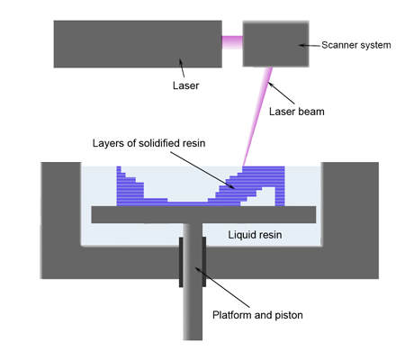
Stereolithography is an additive manufacturing process. Here again, the product is build layer by layer. The machine contains a UV laser and a resin bath. The UV laser traces a pattern of a layer, exposure to the UV laser light solidifies the resin, and makes it adhere to the layer below. The 3D model is build and a final step is to clean the excess resin. This is done in a chemical bath. Finally the object is cured in a UV oven. The technology is mostly used early in the design process.
Selective Laser Sintering (SLS)
SLS is a rapid prototyping technique which uses sintering as it's main process. A CO2 laser fuses small particles of material together to create a layer of an object. When the layer is finished, the layer bed is lowered an another amount of powder is added on top. The laser fuses the next layer here again, repeating this till the product is completed. The exess powder needs to be removed, and some surface finishing may be needed. The layers have a thickness of about 0.15 mm. This process can create prototypes of huge dimensions. For example, total car dashboards can be manufactured.
Traditional Models
Traditional models are commonly made using one of the three main techniques, addition of materials, substraction of materials, or a mix between those two. Many materials can be used. Paperboard and paper are mostly used in architecture models, but they can be used for products very well too. Adventages are the costs and manipulability, though it's almost impossible to create curves. Paper is used very early in the design process. An other material which is used very often, is foam. There are many types of foam, differing in hardness. Foams are good for organic shapes, and they are fast and cheap. Wood is rigid, durable, and there are many types with different properties. Other possibilities are many types of resins, and laminating by hand.
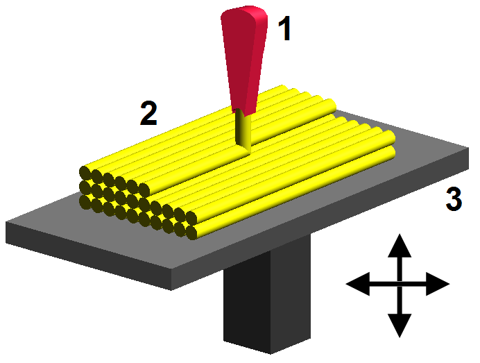
Z-Printer
The Z-Printer builds the prototype by making many thin cross sections of the model. A printerhead moves around the layer to deposit liquid binding material. A thin layer of powder is spread on top of this layer, and the process repeats. The exess powder is automaticly removed by the machine. Main advantage of using this method is the possibility to add color to the product. This allows you to representate different materials held by the product.
General Opinion
Using previous listed rapid prototyping techniques can give you big advantages during the design process. Especially when they are used early in the process, they can prevent errors. Thereby it prevents you from paying a lot of money to repair the error later in the process, because this relation between time and costs is almost exponential. Of course, using these techniques can cost you some money, especially when u use techniques like SLA, SLS, FDM, LOM, and the Z-Printer. However, these costs are negligible when you think of the money you are saving, due to the early detection of errors. Not only the technical aspects are benefits, also aesthetic point can be taken into account. The models are perfect for use in public exhibitions, or to show your operator what your ideas are. Physical interaction with products always gives us a better experience with the product, than just graphical images and explanations. Most of these techniques have become a standard prototype manufacturing process, but I think there is a lot more to come. There is still much improvement possible in this area, like I stated in my first post of this blog. Let's also not forget the 'simple' way of making prototypes, like with materials as paper and cardboard. Those materials give us the opportunity to create quick and cheap representations of the design. Like I said before, physical interaction lets you experience the product way more than just visual interaction. Sometimes you see the first sketches and prototypes of famous architects and designers, and they look so plain and straightforward, sometimes even childish. We shouldn't forget the easy ways early in the process. I would like to end with a sketch of the famous architect Frank Gehry, who designed buildings including the Guggenheim Museum, Walt Disney Concert Hall, Dancing House, and many more. You can see the simplicity of designing in his sketches.
A microscribe is a device for tracing over the contours of an existing object. You can capture the physical properties of three-dimensional objects and translate them in to your own 3D model. The microscribe is build out of a three joint arm, with a stylus at the end of it. The joints give you the freedom to move the stylus in all the directions you would like, making it able to trace your object in all kind of directions you want to. This method provides a fast and easy-to-use way of creating an accurate 3D model.
Microscribe in use
To trace a model you have to move the stylus to the place you want to define as an existing point of the product. You should place your stylus at the beginning of an arc you would like to trace, and confirm the point by pushing the pedal. Those pedals are controlled by your feet. Continuing to confirm points can result in an array of points, which you can convert into a curve later on. Depending on the software which is used you can also draw curves right away, like in Rhinoceros.
You should draw a mesh on your product when it contains complex curves. At the crossing of lines and along hard edge lines, points can be digitzed and curves created through them. Filling those curves with planes will result in a 3D model of the traced object.
I think, thinking in prototypes rather then only sketching is certainly a promising way of designing a product. However, I have more faith in a hybrid way of designing with prototypes. Thinking in prototypes as described in the article written by Bart Eisenberg uses the prototypes merely to evaluate the state of the product at that point. It creates prototypes which you can evaluate in their 'future environment', you can hand out prototypes to people who are going to use the product, and you will get to know how they experience the product. In this way you will eliminate early errors you wouldn't find with just sketches, which is really a good thing. At those points I totally agree with the article, but why not take it a step further?
In my opinion there must be a way to get even more advantage from the prototypes. We should create a hybrid way of designing with prototypes. At my home university they are working on a project called 'Raw Shaping' (rawshaping.com). They are creating a new way of designing shapes, we should be able to change the prototypes right away, and just keep changing it till we are pleased with the result. At this point you could even use the help of future consumers of the product, and let them interfere with the design process. Those are the people who will have to use the product, their opinion should be the most important one. In this movieclip you can see the process of 'Raw Shaping'.
As you can see there is an hybrid way of designing, using the clay and computer. You can use the clay to do the raw shaping and the computer to do the fine-tuning. I think this will be very usable for all kinds of prototypes, a hybrid link between the prototype and the CAD design on the computer. In this way you can create dozens of shapes, fast and easy adjustable, and store them on your computer. I think designing is at first a tactile process, seeing and feeling the shape in reality means so much more then just looking at a 3D model on a screen. Adjusting a shape with your hands, feeling the result and repeating this process till you're satisfied, it's such a fast way of designing a raw shape.
The adjusting of the shape is actually the same thing as what Lenny Lipton calls 'trial and error', but I see no point in manufacturing dozens of prototypes, we should use them in the design process, as a design tool. Of course, you need different types of prototypes, and not all of the prototypes are as easy to adjust as the clay shown in the movie, but some people think there is a solution to that problem. This solution is called 'Claytronics', I could explain it myself, but it's easier to watch this movie:
This maybe sounds impossible, and maybe it is, but I'm sure there are ways to get even more advantage from prototypes used in a design process, they will become part of the process, maybe in the far future they will be the process itself.
As you can read I really admit that prototypes should be part of the design process, but lets not forget the pencil too. I still like to sketch and find forms with my pencil, and I think it will take a lot of time and technical improvement to eliminate the need of the pencil out of the design process. As for now, rapid prototypes are an effective and efficient way of evaluating the current state of the product, and they make it possible to eliminate errors early in the design process. However, there should be many more possibilities to make the use of prototypes part of the design process, they will become essential to future designers.